Understanding 3-Way Switches
A 3-way switch controls a light fixture from two different locations, adding convenience and safety to your home. This guide provides clear, step-by-step instructions and diagrams for wiring a 3-way switch in various configurations.
Before You Begin: Safety First
Turn off the power at the breaker box before working on any electrical wiring. Double-check the power is off using a non-contact voltage tester. If you’re uncomfortable working with electricity, consult a qualified electrician.
Tools and Materials
- Two 3-way switches
- 14-gauge wire (or as required by local electrical code)
- Wire strippers/cutters
- Phillips head and flathead screwdrivers
- Needle-nose pliers
- Electrical tape
- Wire nuts (wire connectors)
- Non-contact voltage tester
- Multimeter (optional, for troubleshooting)
Wiring Diagrams and Instructions
Three common 3-way switch scenarios exist, each requiring a slightly different wiring approach. Downloadable, color-coded diagrams for each scenario are provided below:
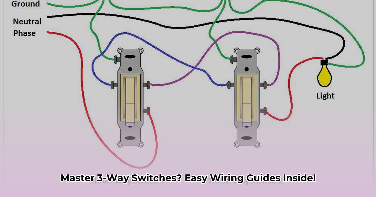
- Diagram 1: Power at Switch 1
- Diagram 2: Power at Light Fixture
- Diagram 3: Light Fixture Between Switches
Scenario 1: Power at Switch 1 (Power-In)
-
At Switch 1: Connect the incoming black “hot” wire to the common terminal screw (usually black). Connect two “traveler” wires (typically red and black, but avoid white or green) to the remaining two terminals. Connect all white neutral wires together with a wire nut. Connect all ground wires together.
-
At Switch 2: Connect the traveler wires to the corresponding terminals on the second switch. Connect the black wire running to the light fixture to the common terminal. Connect all neutral and ground wires as in Step 1.
-
At Light Fixture: Connect the black wire from Switch 2 to the black fixture wire. Connect the white neutral wire to the white fixture wire.
Scenario 2: Power at the Light Fixture (Power-At-Light)
-
At Light Fixture: Connect the incoming black “hot” wire to the black fixture wire. Connect the incoming white “neutral” wire to the white fixture wire and to the white neutral wires running to both switches. Connect all ground wires together.
-
At Both Switches: Connect the black, red, and white wires from the 3-wire cable to their corresponding terminals (black to common). Connect the ground wires.
Scenario 3: Light Fixture Between Switches (Middle-of-Run)
This setup requires careful attention to the traveler wires. Refer to Diagram 3 and follow these general steps:
-
At Switch 1: Connect the incoming hot wire or the wire running to the light (depending on the power source) to the common terminal. Connect traveler wires to the remaining terminals. Connect the neutral and ground wires. Many suggest the red traveler wire from the light fixture.
-
At Switch 2: Connect the traveler wires to their corresponding terminals. Connect the wire going to the light fixture to the common terminal. Connect the neutral and ground wires. Black wires from both the power source and the light fixture.
-
At Light Fixture: Connect the wires from both switches and the power source (if applicable) according to the diagram. Connect the neutral and ground wires.
Troubleshooting
-
One Switch Doesn’t Work: This probably suggests a problem with the switch itself. Try replacing the faulty switch.
-
No Lights: Check the breaker. Try a new lightbulb. Inspect wire connections for looseness. Use a multimeter to test switch connections. The issue may be a disconnected common wire or problems within the electrical system.
-
Flickering Lights: This usually indicates a loose connection. Tighten all screws on switches and in the light fixture box.
Tips and Best Practices
- Use Color-Coded Wires: This simplifies wiring and troubleshooting.
- Label Wires: Clearly labeling wires with electrical tape helps identify them later.
- Use Push-In Wire Connectors (Optional): These can make connections easier.
- Sketch a Diagram: Draw a diagram of your setup inside the switch box for future reference.
Glossary of Terms
- Traveler Wires: The two wires connecting the 3-way switches, enabling communication between them.
- Common Terminal: The terminal on a 3-way switch where the power source or the wire to the light fixture connects.
FAQ
Q: Can I use 12-gauge wire for 3-way switches?
A: Using 12-gauge wire depends on the circuit amperage and local electrical codes. Consult an electrician to determine the correct wire gauge. Using the wrong gauge may pose a fire hazard.
Disclaimer
This guide is for informational purposes only. Consult a qualified electrician for any electrical work. Incorrect wiring can be dangerous. While this information is current, ongoing research, particularly in areas of smart home technology, may lead to evolving best practices in wiring 3-way switches. Therefore, checking up to date guides and recommendations according to your local code is encouraged. The information presented here reflects current understanding but does not account for future developments.
Note: Adherence to the National Electrical Code (NEC) and local electrical codes is crucial for safe and compliant wiring.

- How to Get Motor Oil Out of Clothes: Proven Methods & Step-by-Step Guide - April 25, 2025
- How to Get Mothball Smell Out of Clothes: A Complete Guide - April 25, 2025
- How to Get Highlighter Out of Clothes: Easy & Effective Stain Removal Guide - April 25, 2025